News
As a logistics visualized supply chain management solution provider focusing on the field of wireless communication.

AOVX tracker solutions Crop. developed wireless sensor monitoring creatively integrates the three elements of “people”, “goods” and “warehouses” in the logistics supply chain into one platform.
The device with a wide range of application scenarios, like ocean shipping tracking 、Vaccine transportation、Vehicle monitoring, etc...
As a component of the Aovx tracking device, the TVS tube's main function is circuit protection and preventing static electricity from damaging Aovx tracking equipment.
Do you know the basic usage of TVS tubes? Let's learn more about TVS tube via the Aovx hardware workshop.
Basic use of TVS diode
TVS (Transient Voltage Suppressor), also known as Transient Voltage Suppressor, is a solid-state component used to absorb ESD energy and protect chips or systems from ESD (Electrostatic Discharge) or Surge damage. Generally used in the front end of the protected system, the protection voltage is slightly higher than the rated voltage of the protected system, but lower than the maximum withstand voltage of the system. The commonly used TVS tubes are divided into unidirectional and bidirectional, as shown in Figure 13-1.
Unidirectional TVS is generally used in DC circuits. The forward characteristic of unidirectional TVS is the same as that of ordinary Zener diode, which is a typical PN junction avalanche device. The curve segment from the breakdown point to the VC value shows that when there is an instantaneous overvoltage pulse, the current of the device increases sharply and the reverse voltage rises to the clamping voltage value and keeps the voltage basically unchanged. The bidirectional TVS can absorb instantaneous large pulse power in both positive and negative directions, and its on-resistance is very small to discharge the surge pulse of the positive and negative electrodes, and clamp the voltage to a predetermined level, which is suitable for AC circuits.
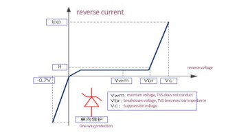
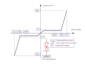
Figure 13-1
When we usually design circuit systems, which TVS devices need to be added? For example, some data interfaces or power interfaces with plugging and unplugging functions, such as USB, RS485, USIM card, charging terminal, etc., adding TVS devices can prevent the static electricity caused by similar plugging and unplugging actions from affecting the system; there are also radio frequency antenna terminals, Mic/speaker Interface, button interface, LCD interface, etc., adding TVS can also prevent the introduction of static electricity. In addition, circuits with transient inductive switching changes also require the addition of TVS devices.
For electrostatic protection, the following three categories are mentioned in the International Electrotechnical Commission IEC61000-4 standard:
① Electrostatic discharge IEC61000-4-2 (ESD): Air-15kV, Contact-8kV.
② Transient pulse IEC61000-4-4 (EFT): 40A-5/50ns.
③ Surge pulse IEC61000-4-5 (Surge): 24A, 8/20us-Level 2 (Line-Gnd) & Level 3 (Line-Line).
In the ESD requirements of ①, the device under test needs to meet the air discharge of 15kV, that is, the direct discharge test operation is performed on the insulating surface of the product, such as the shell, etc.; the device under test needs to meet the contact discharge of 8kV, that is, the conductive surface of the product is tested. Direct discharge test operations, such as exposed charging interface metal, etc. This is also the anti-ESD capability that basically all end products need to meet.
In the requirements of ② and ③, we can see the time of 5/50ns and 8/20us, we use T1/T2 instead, as shown in Figure 13-2.
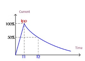
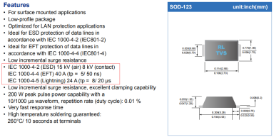
Figure 13-2
Basically, some interference tests such as static electricity and lightning strikes of the product are tested according to this waveform. T1 represents the rising period, T2 represents the period from the start to falling to 0.5Ipp, and Ipp represents the peak current.
How does the TVS tube protect the system?
Figure 13-3 shows a unidirectional TVS as an example, using a waveform to visualize how the TVS prevents the intrusion of static electricity or surge. At the same time, it is also expressed that the selection of the TVS suppression voltage Vc needs to refer to the maximum transient voltage that the protected system can withstand, and the selected Vc must be less than this maximum transient voltage to protect the system well.
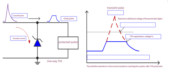
Figure 13-3
Let us introduce the key points that need to be paid attention to when choosing a TVS tube.
①Maintaining voltage Vwm selection: The maximum reverse voltage that the TVS tube does not conduct is at least 10% larger than the highest working voltage of the system.
②Clamping voltage Vc selection: when the pulse peak current Ipp is passed, the voltage across the TVS tube must be less than the maximum transient voltage that the protected circuit can withstand.
③ Selection of maximum pulse power Pppm: the maximum peak pulse power of TVS must be greater than the peak pulse power of the protected system. Depends on the pulse peak current Ipp and the maximum clamping voltage Vc, in addition to the pulse duration, pulse shape and ambient temperature.
For example, the maximum pulse power of a TVS is 600W@10/1000μs, then the absorbed power of a 50ns pulse may reach 2000W, while the absorbed power of a 10ms pulse may only be 200W. In addition, some materials indicate that for pulses in the form of half sine waves, the absorbed power should be reduced to 75%; for pulses in the form of square waves, the absorbed power should be reduced to 66%. Since TVS is also a PN junction device, its reverse leakage current increases with the increase of temperature, so the increase of junction temperature causes the power of TVS to decrease.
④ Selection of capacitance between electrodes: The higher the operating frequency or speed of the protected components is required, the smaller the capacitance of the TVS is. Due to the relatively low speed of the audio interface, the inter-electrode capacitance of the TVS selected can be relaxed to 100pF, and the TVS capacitance requirements at the power interface can be wider. For interfaces with higher speed, such as USB2.0, it is better to need less than 3pF, and for USB3.0 with higher speed, it is necessary to choose TVS tubes below 1pF. The interpole capacitance value of the TVS output from the RF antenna port also needs to be relatively small, which will affect the quality of the RF signal. Table 13-1 roughly gives the requirements for inter-electrode capacitance in circuits with different operating frequencies, for reference only.

Figure 13-4 is taken from a TVS series specification, from which we can correspond to our Vwm and IR, Vc, Ipp and other selection parameters.
In actual circuit design, there are some other devices that can be used for ESD protection. Briefly explain the difference below.
①Ceramic capacitors are used for protection: the main advantage is that the response speed is fast and the cost is very low. However, for the electrostatic voltage pulse of 15kV, the capacitor is basically damaged. Generally, the pulse of 5kV will cause 10% of the capacitor to fail. It can be seen that the protection of ceramic capacitors is not very effective, and even if the capacitor does not fail, its capacitance will change after a pulse.
②Using varistor (MLV) for protection: The main advantage is that the withstand voltage and current withstand capability is higher than that of TVS, and there is no polarity, and the cost is much cheaper. However, the response speed of MLV is slow (MLV is ns level, TVS is ps level), the parasitic capacitance is large, the leakage current is large, and it will continue to age and fail over time.

Learn more about AOVX :
The wireless sensor monitoring technology developed by the AOVX creatively integrates the three elements of “people”, “goods” and “warehouses” in the logistics supply chain into one platform, and conducts all-around data collection and analysis for personnel, goods, and the environment in warehousing and logistics monitor.
Website: www.aovx.com

Latest Posts
Categories
Tags


